Installation
The following procedure details how to install the Electrochemistry (EC) chuck, LakeShore heater (if applicable), and potientiostat for EC applications on the Dimension Icon. Once these steps are complete, refer to Setup Procedures for further information.
- Remove the existing sample chuck.
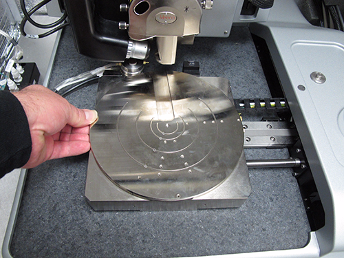
HINT: This may be easier if you move the chuck to the Sample Unload position using NanoScope software.
CAUTION: Use caution not to bump the AFM head.
- Install the Dimension Icon Electrochemistry (EC) chuck:
- Screw the chuck in place using two M3 x 6 mm socket head cap screws and a 2.5 mm hex wrench:
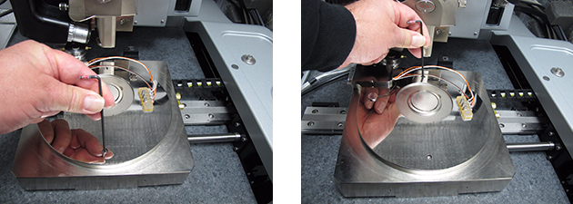
- Attach the DB15 EC extension cable to the Dimension Icon chuck:
- Secure the EC extension cable.
If you have a Dimension Icon Heater/Cooler accessory:
The EC extension cable needs to be attached to the heater/cooler manifold along with the existing heater/cooler cables as shown in Figure 1. This keeps the cables from dragging on the Dimension Icon granite base or the X axis linear bearings as the XY stage moves. You will need to use two larger ½" black plastic cable clamps (included) to attach the DB15 EC extension cable and the existing heater/cooler cable/hoses to the heater/cooler manifold.
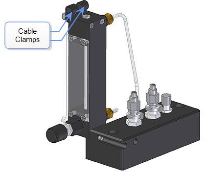
Figure 1: Attach the EC extension cable to the heater/cooler manifold
If the Dimension Icon does not have the Dimension Icon Heater/Cooler accessory:
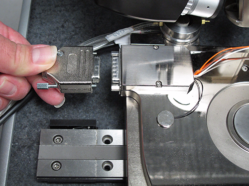
The EC extension cable needs to be attached to the Dimension Icon Cable Guide shown in Figure 2. This guide keeps the cables from dragging on the Dimension Icon granite base or the X axis linear bearings as the XY stage is moved. You will need to use the two 1/4" black plastic cable clamps (included) to attach the DB15 EC extension cable to the Dimension Icon Cable Guide. The cable guide bolts to the left side of the Dimension Icon air table top using two M6 x 20 mm socket head cap screws.
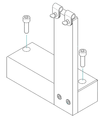
Figure 2: The Dimension Icon Cable Guide
- Ensure that the cable loop is sufficiently long to allow full motion of the XY stage to the extremes of travel and that the cables are oriented in the clamps so that they are not dragging. Nominally the DB15 cable needs to extend about 15" (380 mm) past the cable clamp and the heater/cooler cable and hose need to be about 18" (460 mm) long (see Figure 3).
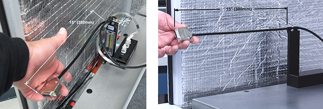
Figure 3: Cable Loop Length (15", 380 mm)
- Rotate the cables in the black plastic cable clamps (as shown by the white arrows in Figure 4) so that the cables do not drag on the XY stage when the moving to the extremes of XY travel.
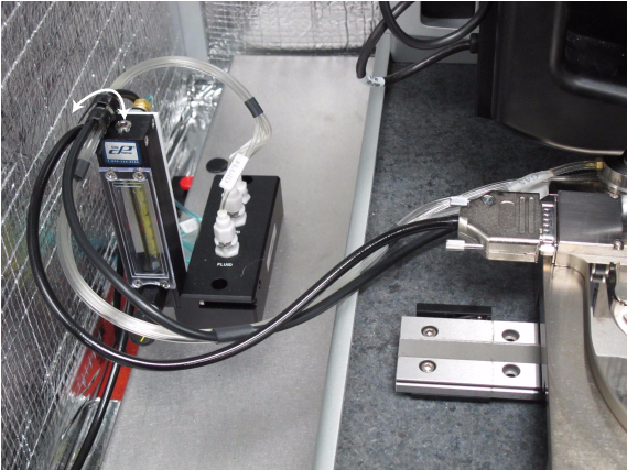
Figure 4: Orient the Cables
- Move the XY stage to the extremes of travel to verify the cable does not drag on the granite or XY stage (see Figure 5). Verify that the cable is not too short and does not stretch at the extremes of travel.
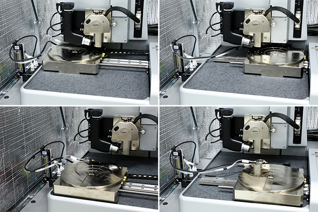
Figure 5: Move the XY stage to the extremes of travel
- If your system is configured with the acoustic hood and/or the Dimension Icon workstation, see the relevant steps below. Otherwise, skip ahead to step 10.
- If the system is configured with an acoustic hood: The DB15 EC extension cable needs to exit the acoustic hood through the left cable clamp as shown in Figure 6. This cable clamp is included with the Dimension Icon Electrochemistry option. For instructions about installing the cable clamp, refer to the document Work Instruction for Unpackaging Icon System (Document Control Number 3PD75144).
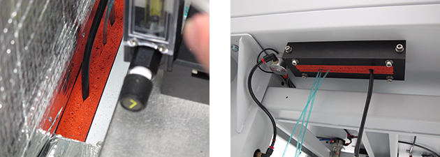
Figure 6: Feed the EC extension cable through the left cable clamp
- If your Dimension Icon microscope includes the Dimension Icon workstation: Run the DB15 EC extension cable under the acoustic hood and to the top of the workstation behind the computer monitor.
- Plug the DB15 connector into the Dimension Icon EC MUX box TO EC CELL connection as shown in Figure 7.
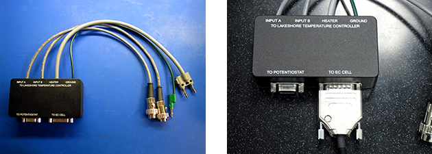
Figure 7: Plug the DB15 connector into the TO EC CELL port of the EC MUX box
- Plug the four integral cables from the EC MUX box into the back of the LakeShore temperature controller, shown in Figure 8 and Figure 9. Use Output 1 of the LakeShore 335 controller. Ensure that INPUT A and INPUT B cables are not reversed.
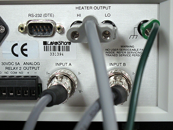
Figure 8: Cables on back of LakeShore 331S
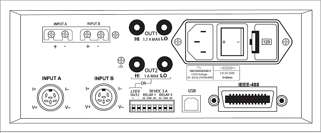
Figure 9: The back of the LakeShore 335
- Connect the DB9 EC Potentiostat cable to the To Potentiostat port of the EC MUX box (see Figure 10).
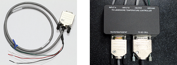
Figure 10: The Dimension Icon EC Potentiostat Cable (left) and Connection to MUX box (right)
- Connect the potentiostat to the DB9 cable. There are two ways to connect to the Working Electrode:
- The working electrode base (pin 4, green wire) connects to the EC cell base itself.
- Pin 1 is the Counter Electrode (black or red wire, depending on MUX p/n).
- Pin 3 is the Reference Electrode (red or white wire, depending on MUX p/n).
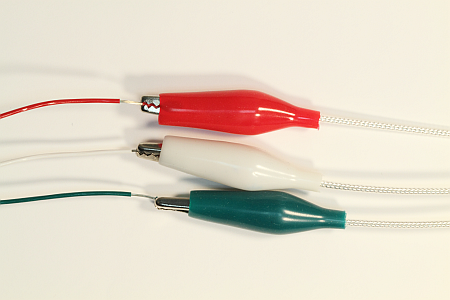
Figure 11: Potentiostat cable (right) connected to DB9 cable (left).
NOTE: The wire colors of the Dimension Icon EC Potentiostat cable may not correspond to the wire colors of your potentiostat:
The EC Potentiostat connections are printed on the bottom of the EC MUX box (Figure 12)
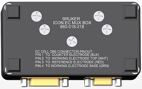
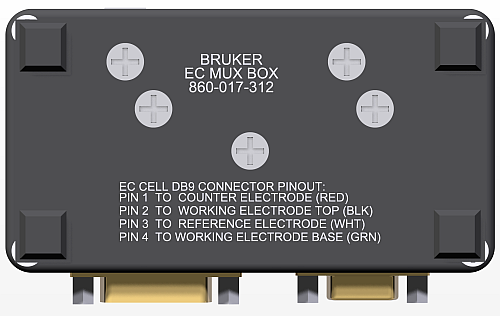
Figure 12: The EC Potentiostat connections.
- Connect the Signals output (in the case on the CH Instruments 760D) of the Potentiostat to the NanoScope V Controller using the DB9-to-BNC cable (p/n 462-000-009), shown in Figure 13
- Connect the blue BNC (E on the CH760D) to Low Frequency Analog Input 1.
- Connect the red BNC (I on the CH760D) to Low Frequency Analog Input 2.
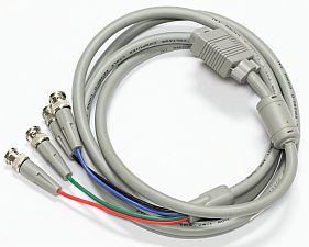
Figure 13: Potentiostat to NanoScope V Controller cable
Proceed to Setup Procedures.
| www.bruker.com
|
Bruker Corporation |
| www.brukerafmprobes.com
|
112 Robin Hill Rd. |
| nanoscaleworld.bruker-axs.com/nanoscaleworld/
|
Santa Barbara, CA 93117 |
| |
|
| |
Customer Support: (800) 873-9750 |
| |
Copyright 2010, 2011. All Rights Reserved. |
Open topic with navigation